Blog: Router Lift, Revisited By: John Heisz
Late last year, when I finished the new router table, I started working on plans for the lift mechanism that I used. Unfortunately, the further I got into it, the more I realized that the lift was really part of the overall router table and would be unsuitable for a stand-alone application (for example: lift mounted in a table saw extension wing). Although some have expressed interest in a complete router table plan set, the majority really only want the lift itself, to put into their own table design.
So, I stopped work on that plan set and gave some thought to making a simple, but very rugged router lift. One of the first things I considered was a scissors mechanism, similar to a car jack (I’ve had a few readers suggest the car jack lift). I rigged it up to try:

It worked ok, but it lacked the range I wanted and had way too many moving parts for my liking.
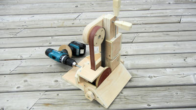
Next I had the “vinyl tube idea”:
Although I started out very hot for this, I quickly lost interest when the negative aspects of this transfer system became obvious. It had a definite lag from input to output, where the hose would twist slightly from the torque applied. This would probably become more pronounced when an actual load was connected, and may become even worse if the hose was warmer – on a hot summer day it’s not exactly cool in my shop. Speaking of cool, or cold (more precisely), the question of how well it would work in sub zero temperatures came up. In the end, just too many unknowns to base a design around.
After the hose, I tried steel aircraft cable in the same configuration. Although this could handle a much tighter radius, it too suffered from the same lag problem and could not transfer anywhere near the same amount of power as the hose without deconstructing (untwisting, if going in reverse).
I went back to the drawing board and thought up a cam type of lift, but this didn’t even make it to a mock-up, since it also had too many moving parts. Next I was playing with a casement window crank…
At that point, it occurred to me that what I was doing was slightly silly, since I had already made the lift system that could easily top all of these other ideas: the simple inclined plane.
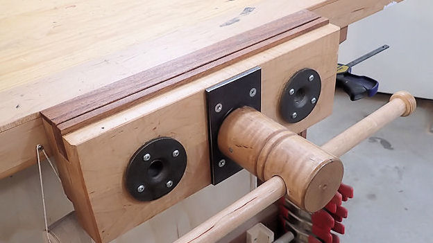
So, I set out to redo the lift design for one that would function without the table, and one that I could get plans together for within a reasonable time frame. Here’s how it turned out:


The rods for the up / down crank and locking handle can be extended out as far as needed.
Although this may look complex, it is actually very simple and quite easy to build. It is made almost entirely of plywood – 1/2″ and 3/4″ with no exotic parts. Standard hardware throughout and the only thing that you may not find at your local hardware store is the single sealed bearing (3/8″ ID, 7/8″ OD). I will be making this part available for purchase (eventually, you know it), after the plans are finished.
This lift is solid and will rigidly hold the router during operation. That is the one thing I see that I feel is lacking in some of the other router lift designs (even commercial ones) that I’ve looked at – they seem to be rather flimsy and will allow vibration that can cause the router to chatter.
If you’ve experienced chatter while making a cut, you know what I’m talking about. It happens when the router can move, even a slight amount and can be quite destructive and scary. So, if there appears to be more wood in this lift than necessary, that would be the reason.


